Construction of Experimental Area
In the fall of 2002, we prepared the sub-base for the installation of the infill systems. 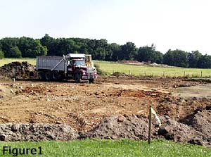
The topsoil was stripped from the site and the subsoil was compacted (Fig 1).
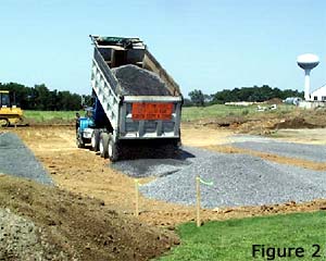
A 4 in. layer of gravel (Fig. 2) was installed.
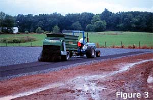
After the gravel was graded and compacted, a 0.75 in. layer of a fine gravel containing appreciable coarse sand (Fig. 3) was topdressed over the area.
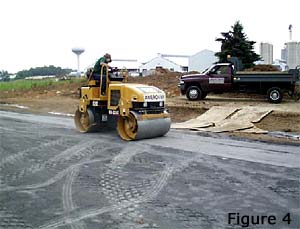
This allowed a more precise grade to be created (Fig. 4).

When the sub-base was complete, various companies marketing and installing infilled synthetic turf systems arrived at The Joeseph Valentine Turfgrass Research Facility at Penn State, and began installing their systems. Most installed nailers around the perimeter of their plots (Fig. 5).
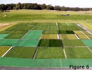
Each product was installed in three 15 ft by 15 ft plots in random locations. All measurements and data reported in this document are the average of values obtained from the three locations (Fig. 6).
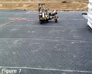
Some companies installed a shock-absorbing pad and some did not (Fig. 7). The three systems containing pads were: Astroplay, Nexturf, and Sofsport.
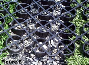
One company, Geoturf, installed an underlying grid that can be used to circulate heated or cooled air throughout the system (Fig. 8). No forced air circulation was done during this study but the effect of the underlying grid on playing surface characteristics was of interest.
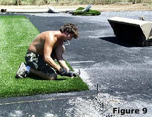
Next, the backing with the upright fibers (pile) was attached to the nailers. (Fig. 9).
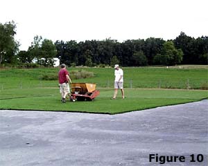
The infill material was then topdressed onto the plots using a traditional topdresser. (Fig. 10).
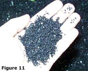
Infill materials varied. Some contained a mixture of sand and crumb rubber while some contained 100% crumb rubber (Fig. 11).
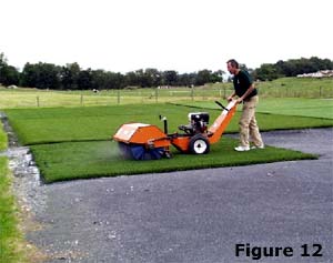
The crumb rubber was then worked into the pile using a power broom (Fig. 12). More infill was topdressed and power broomed. This process continued until the desired depth of infill was installed. The depth of the infill, for each product, is reported in Table 1.

